
MARCONI’S WIRELESS TELEGRAPH COMPANY LIMITED
Head Office: Marconi House, Chelmsford ∙ Telephone: Chelmsford 3221 ∙ Telegraphic Address: Expanse, Chelmsford
Mobile television
THE TECHNIQUE of outside broadcasting, so successfully introduced into sound radio, has naturally found its consummation in the field of television. The presentation to the public, in their homes, of ‘live’ happenings in the outside world, such as national events and highlights of sport and entertainment will always provide an unfailing source of popular programme material to television producers. The scope of this resource is limited only by the degree of versatility and technical capability of the equipment used to capture these topical items and feed them to the transmitter.

In city, town or country, the quality of picture and sound produced by Marconi television equipment is unsurpassed.
The Marconi mobile television unit not only provides a means of conveying the camera to the event, but is in itself a complete television studio with full facilities for the artistic production of a programme from a number of camera channels and sending it direct to the broadcasting transmitter. An attractively economic possibility is therefore presented of producing a programme entirely from mobile units, without the use of permanent studios.
In city, town or country, the quality of picture and sound produced by Marconi television equipment is unsurpassed.

Typical schedule of equipment
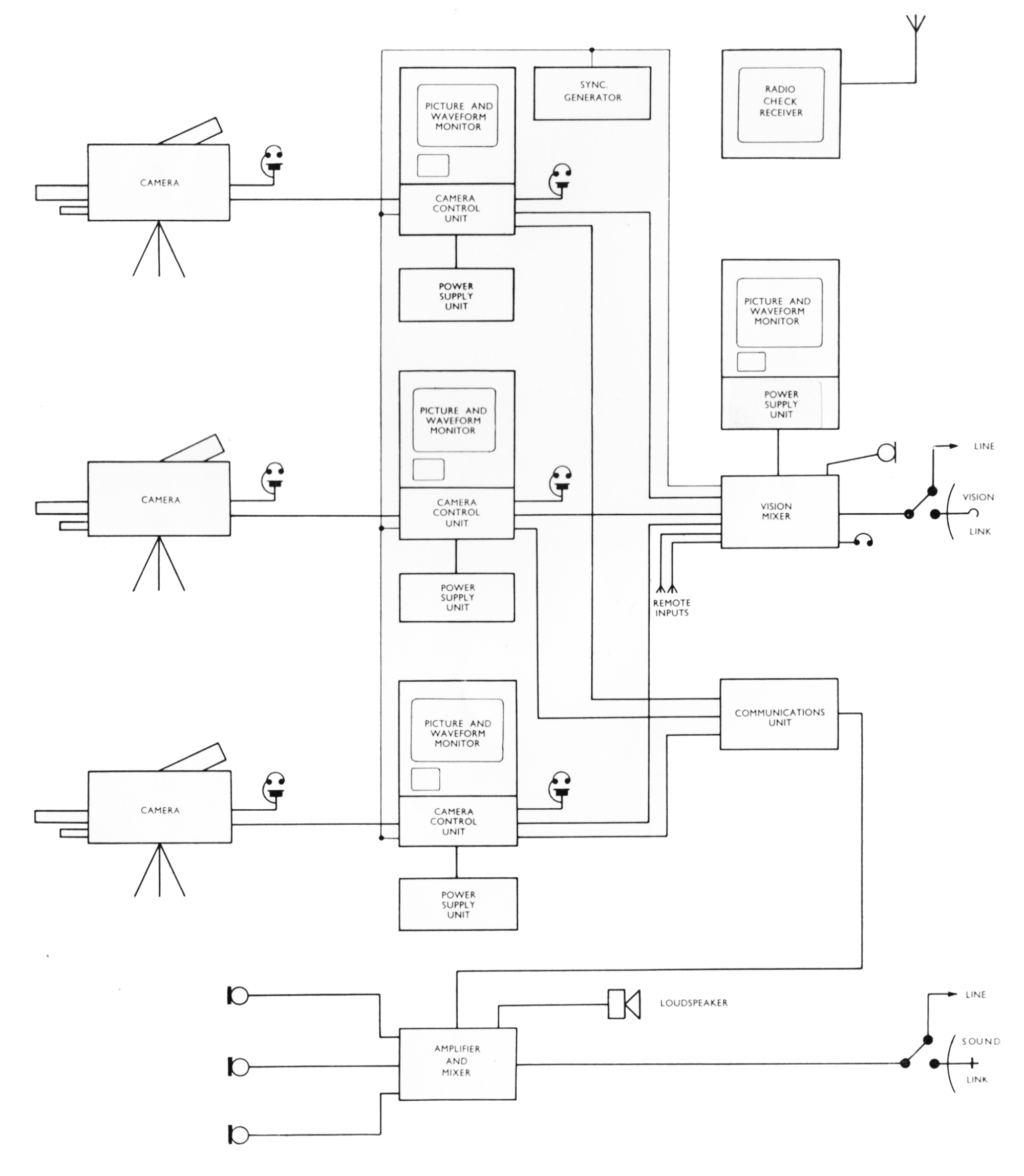
Representative of equipment commonly incorporated in a mobile television control room
| Quantity | Item | Reference |
|---|---|---|
| 3 | IMAGE ORTHICON CAMERAS | A |
| 3 | CAMERA CONTROL UNITS | B |
| 4 | PICTURE AND WAVEFORM MONITORS | C |
| 3 | REGULATED POWER SUPPLY UNITS | D |
| 1 | MONITOR REGULATED POWER SUPPLY UNIT | E |
| 1 | FOCUS SUPPLY UNIT | F |
| 1 | VISION MIXER (includes line clamp amplifier) | G |
| 1 | RF MONITOR | H |
| 1 | SYNCRONISING GENERATOR | J |
| 1 | COMMUNICATION UNIT | K |
| 1 | LOUDSPEAKER | L |
| 1 | CENTIMETRIC SOUND LINK | M |
| 1 | CENTIMETRIC VISION LINK | N |
| 1 | VOLTAGE CONTROL UNIT | O |
| 1 | DISTRIBUTION AND TERMINATION PANEL | P |
| 1 | RECEIVING AERIAL | Q |
| 1 | PETROL-ELECTRIC GENERATING SET | R |
Sound control equipment comprising
| 1 | CONTROL PANEL | S |
| 1 | MOBILE AMPLIFIER UNIT | T |
| 1 | POWER SUPPLY UNIT | U |

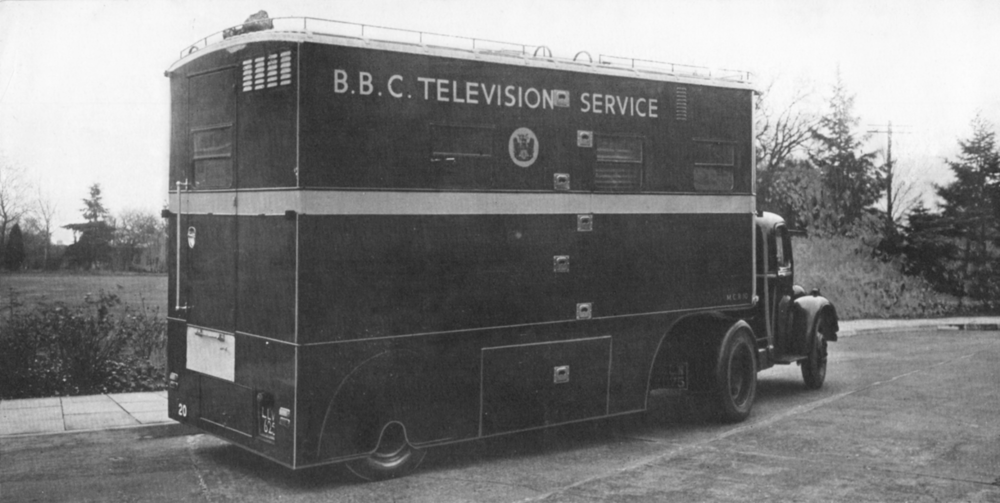
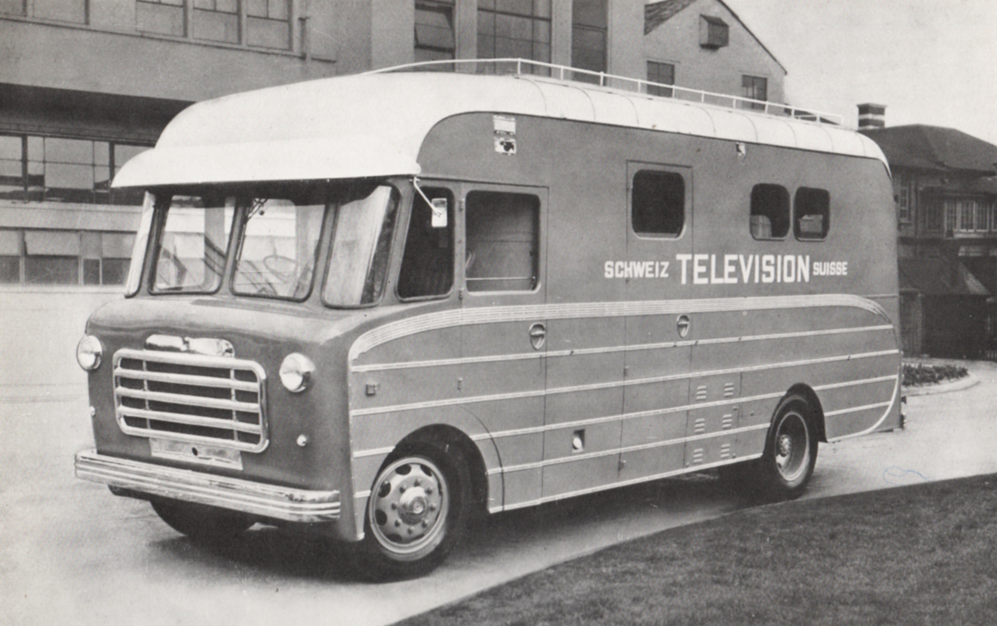
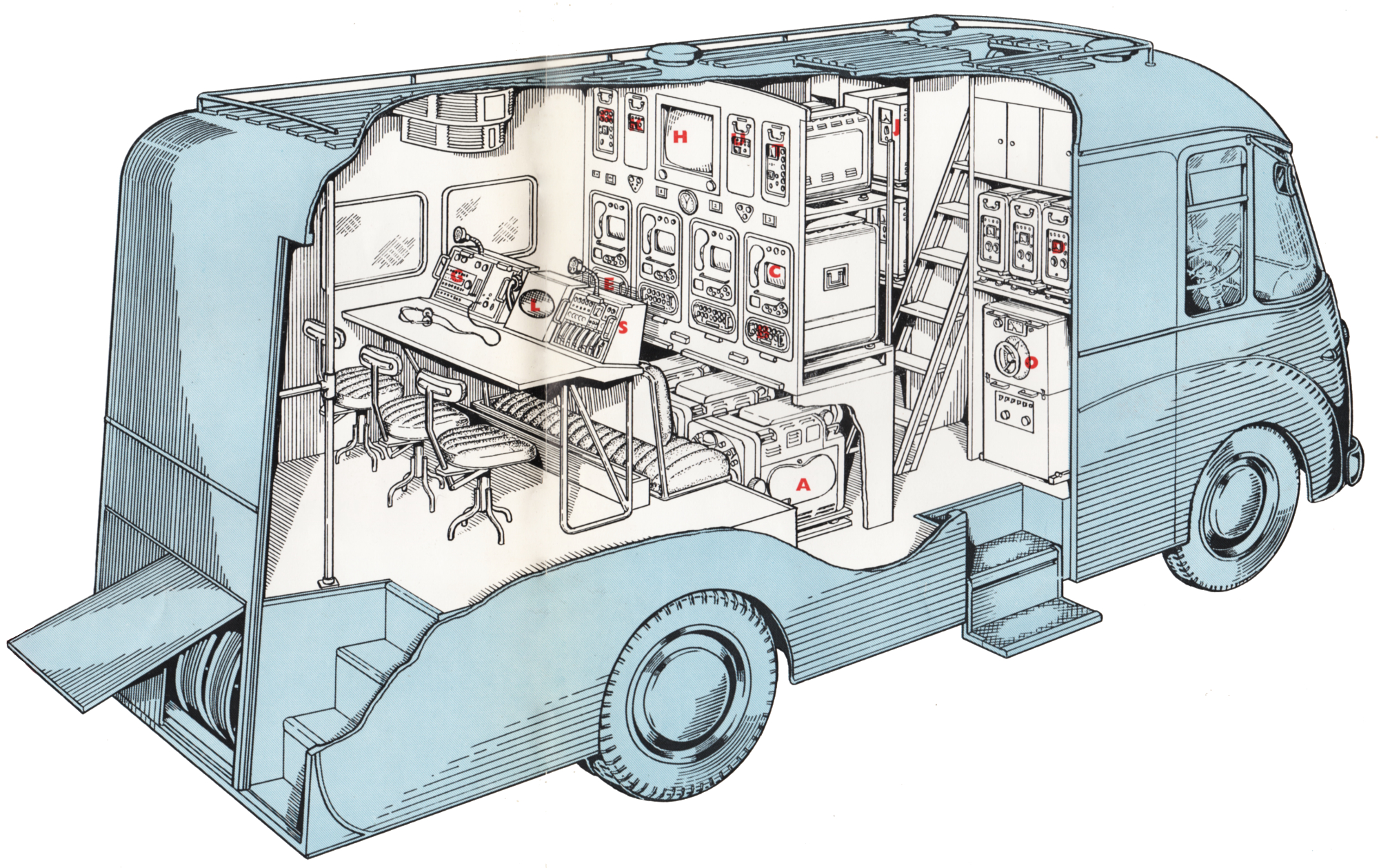
Sectional view of a model of a current design for the B.B.C, the vehicle itself being depicted below
Basic Equipment
Each television mobile control room is equipped with two or three mobile image orthicon camera channels, type BD808, as well as vision and sound mixing apparatus and associated power supply equipment. This camera channel gives the highest technical performance combined with maximum operating facilities.
Television Camera Type BD687
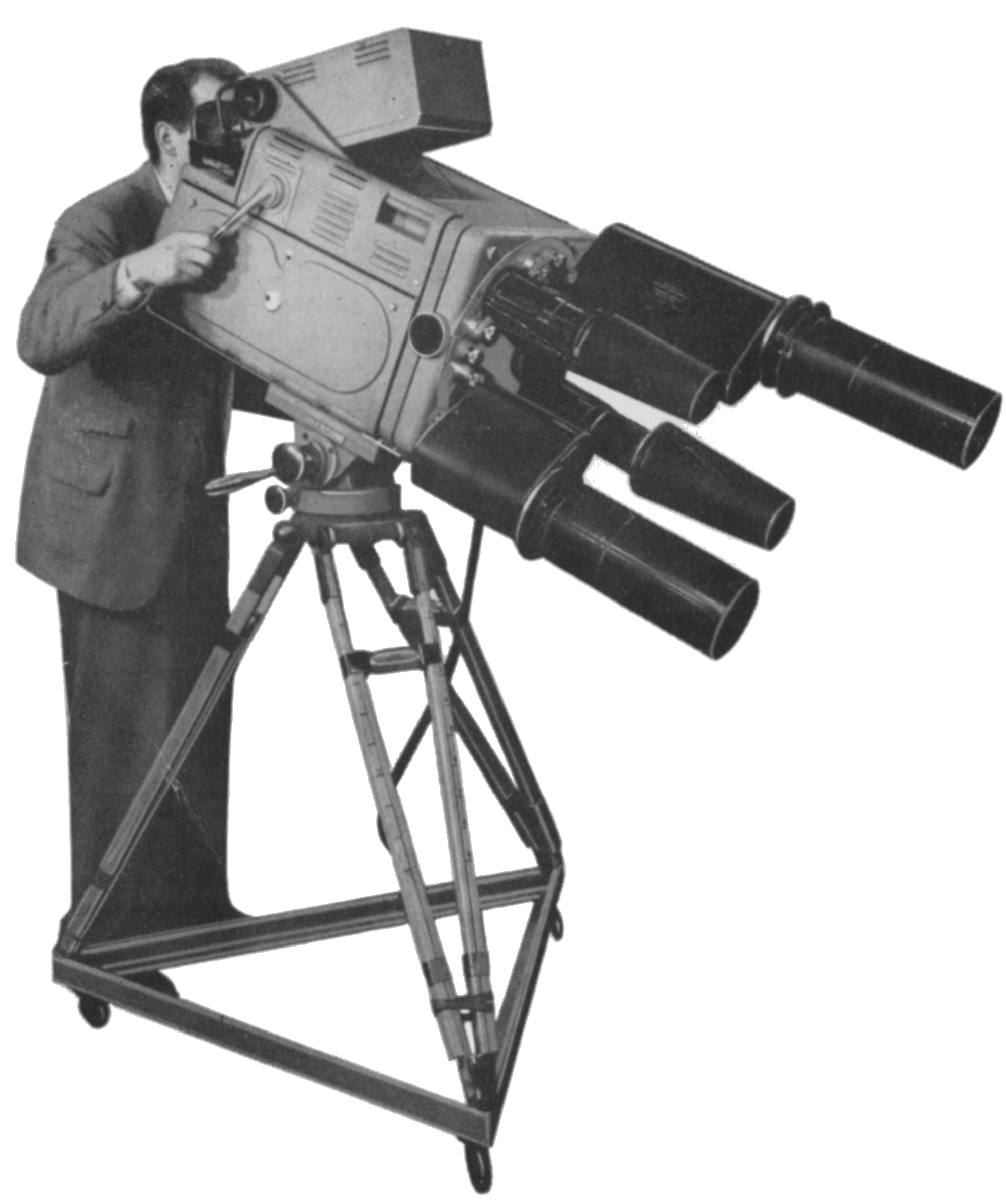
THE CAMERA is built in two basic versions to permit the use of either a 3-inch or 4½-inch image orthicon tube. A feature of the camera is its lens turret. This will carry four lenses which may be any combination from 2-inch to 40-inch lenses. A zoom lens and an 80-inch lens may also be used and with both 40- and 80-inch lenses in position the turret may still be rotated with ease, the mechanical handling of the camera being exceedingly fine. Light intensity control is by means of a variable graded filter which replaces conventional remote iris control methods. This control may be carried out from the camera control position. Televising at difficult angles is greatly facilitated by the counter-poised viewfinder which may be moved independently on the camera and so allows operating ease with the camera pointing at sharp angles. The sensitivity of the camera is such that it will operate with as low as 1-ft. candle incident illumination making it ideal for outside broadcast use.
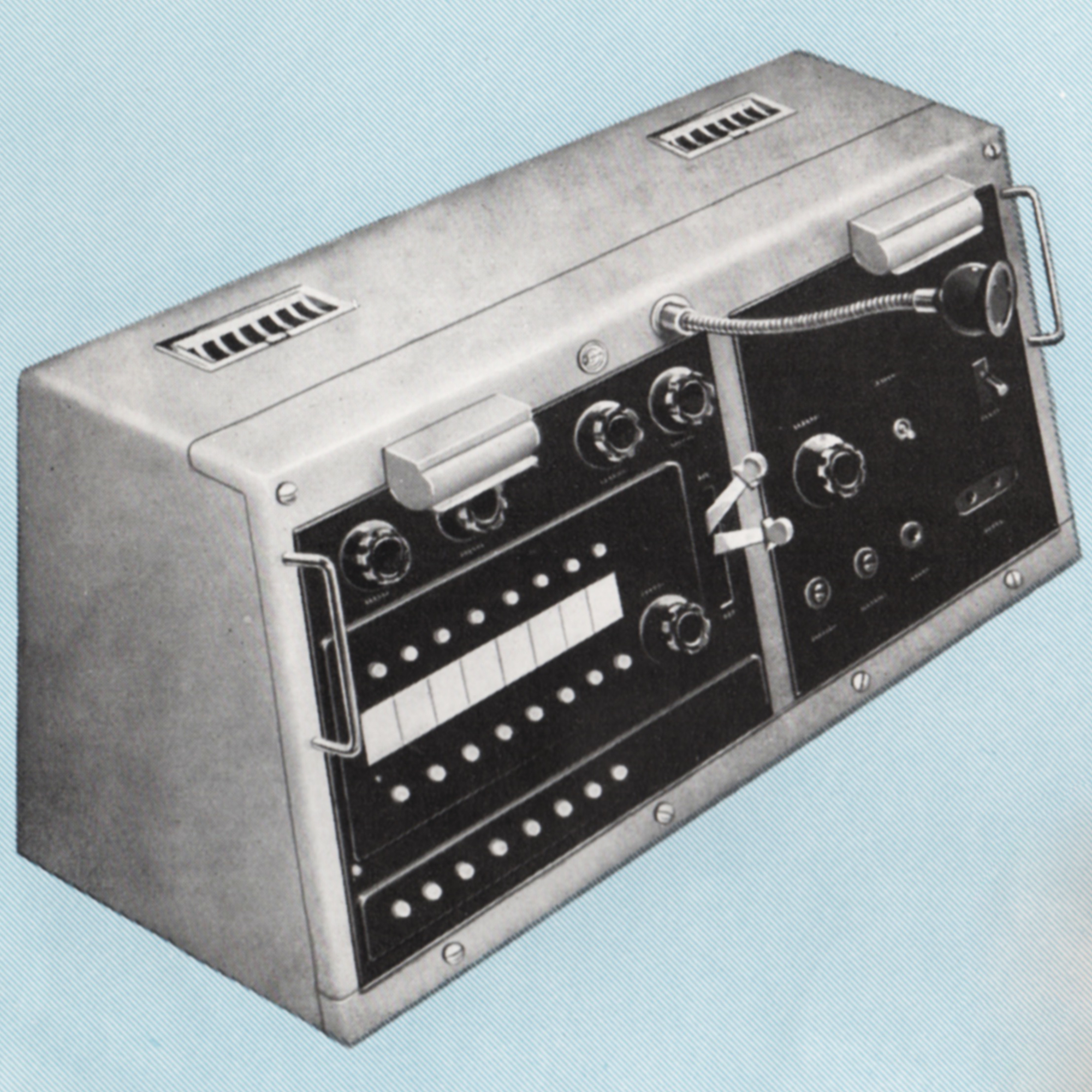
Camera Control Unit
THE CAMERA control unit contains the necessary control and amplifier circuits for the camera. It is normally associated with a picture and waveform monitor, the two units being assembled together to form a control position for each camera channel.
Signals are fed from this unit to the vision mixer, the camera viewfinder, and the monitor. Communication facilities are also provided between cameraman and camera-control operator.
Picture and Waveform Monitor
DESIGNED FOR a variety of uses the picture and waveform monitor incorporates a ten-inch picture tube and a five-inch waveform tube. One such unit is employed at each camera channel control position and a further monitor serves as a production monitor when used in conjunction with the vision mixer.
Vision Mixer
THE MIXER is suitable for desk mounting in the producer’s position. It provides facilities for cutting, mixing and fading between seven inputs. Four outputs plus a monitoring output are available. Direct switching is employed, together with bias fading.
Synchronising Generator
THE SYNCHRONISING generator provides the synchronising and blanking pulses, and the line and field driving pulses for the system. Electrically the circuits divide into two — those providing the timing information and those generating the required waveform. For the sake of convenience the synchronising generator used on 525 and 625 line systems is divided physically into two corresponding chassis: that used for405 line operation, however, is one unit.
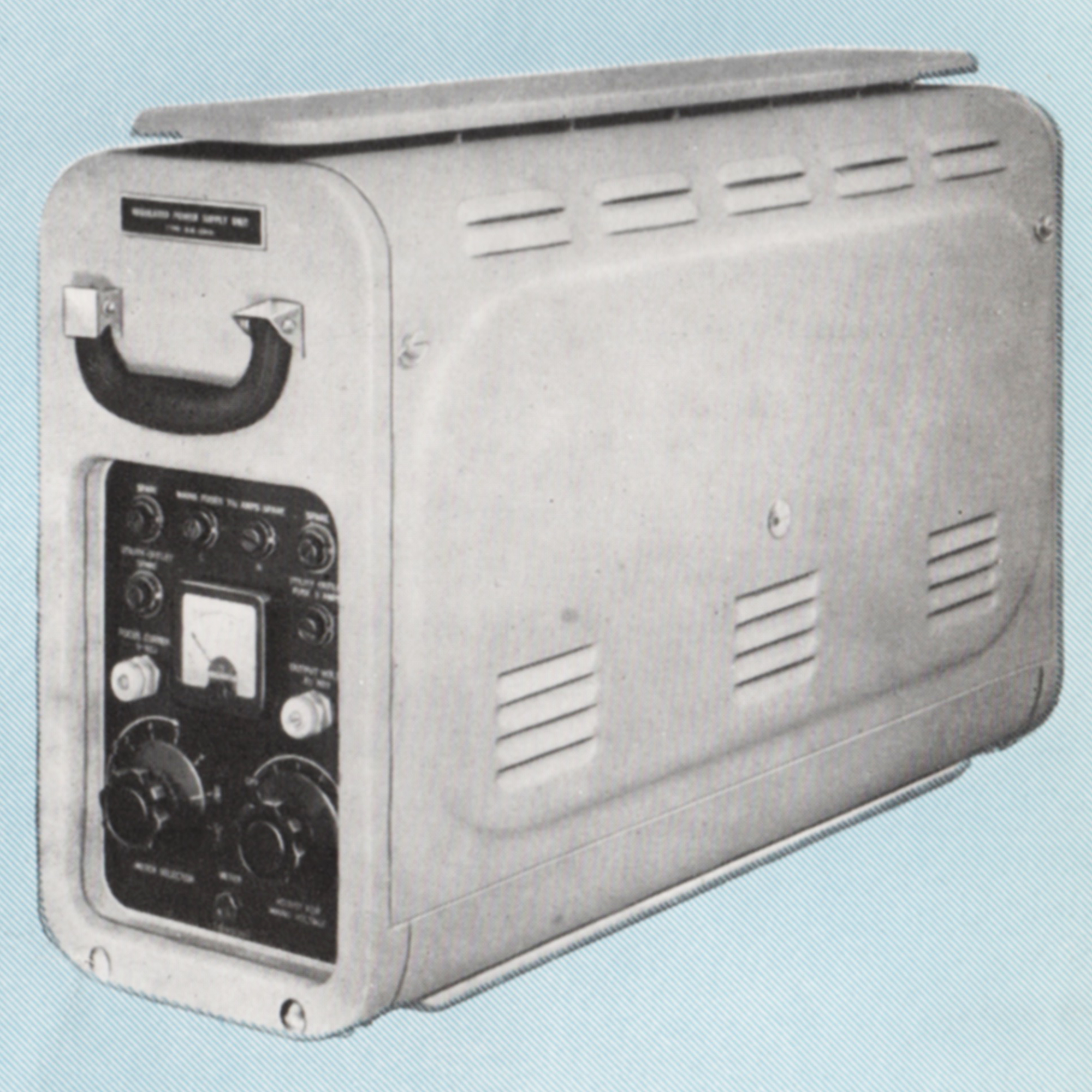

Regulated Power Supply Unit
EACH CAMERA channel has its own power supply unit which is designed to provide all AC and DC supplies, part of the DC output being electronically regulated. Facilities are provided on this unit for mains input transformer tap changing to give maximum flexibility in operation, so permitting a camera channel to be operated remote from the mobile unit.
Focus Supply Unit
UP TO FOUR focus supply units may be assembled in one case for mobile applications. Each unit comprises a small panel which supplies power to the focus coils of the camera.
RF Monitor
HAVING a 17-inch picture tube, this unit is used as an RF check receiver for cueing and general monitoring purposes.
Sound Control Equipment
SPECIALLY designed for television OB work, this equipment comprises three main items—an amplifier unit, a power supply unit and a control panel. Facilities are provided for the control of five low-level and two high-level inputs with high-level mixing. Prefade listening on all input channels is possible and two independent outputs are available. In operation, all control is carried out from the control panel which is similar in appearance to the vision mixer. Quadrant-type faders are used and each fader has an associated visual indicator.
Communication Unit
OPERATING personnel need to be in communication with the producer and other members of the production team, and similar facilities are required between the camera and control positions for technical purposes. The communication units, of which several types are available, serve to provide the necessary facilities.
Centimetric Vision Link
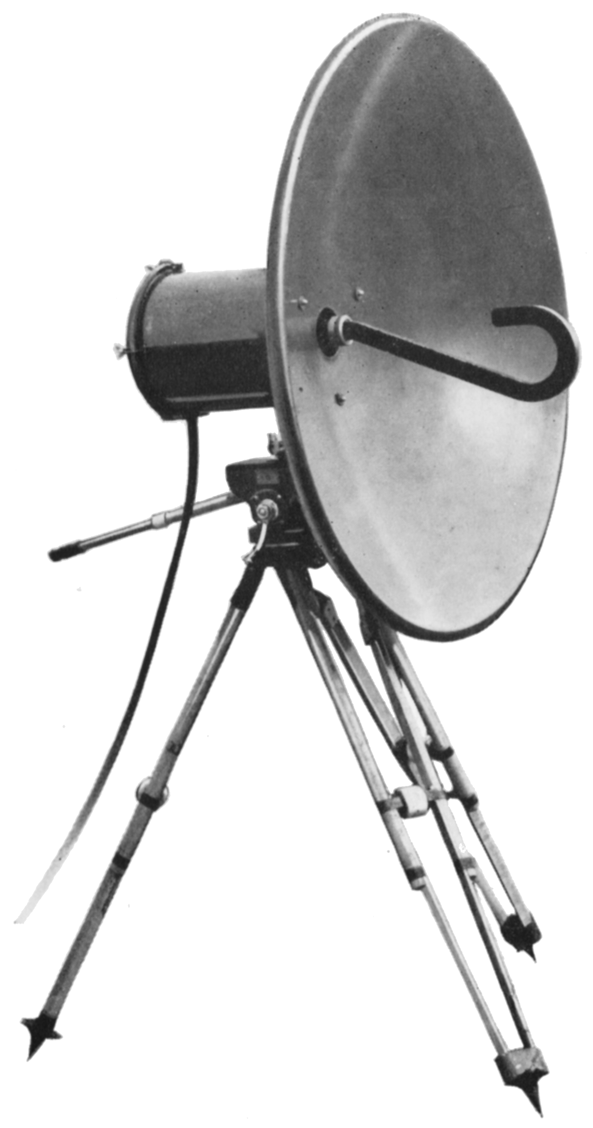
FOR PROGRAMME relaying between a remote pickup and the main studio centre, the centimetric link is ideally suited. The ultra-short operating wavelength, of less than 5 cm, enables parabolic antennae with high gains to be used, so giving directional transmission over line-of-sight paths up to 40 miles in length. The equipment includes a control unit and transmitter at the transmitting end of a link and a receiver, control unit and power supply unit at the receiving end.
Centimetric Sound Link
COMPANION to the vision link, the sound equipment comprises transmitter and receiver head units each with its power supply unit, this latter being identical in both cases.
Voltage Control Unit
HAVING a handling capacity of 12.5 kVA, this unit supplies all the power to the vehicle at constant voltage. All circuits are fused and metering and alarm facilities are included.

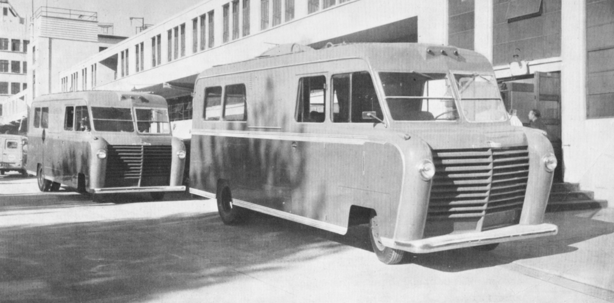
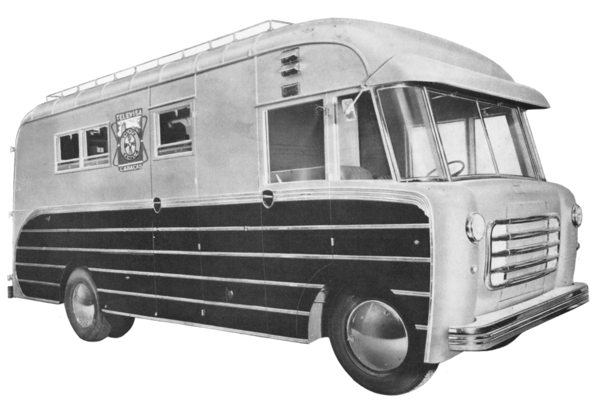
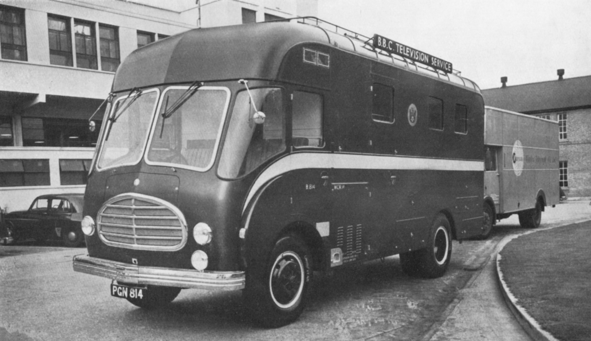
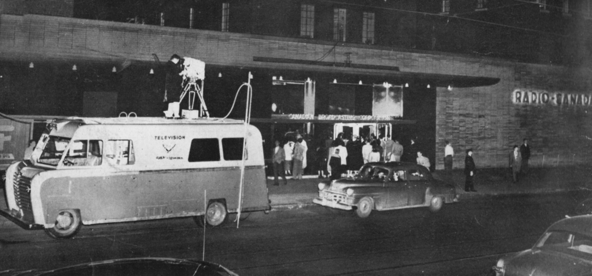
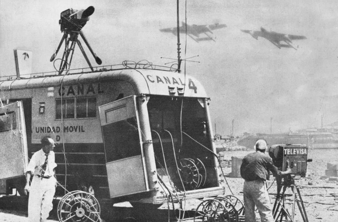
The Mobile Unit
The layout of a Mobile Television Unit will depend, of course, on the type vehicle being used, that is, chassis and type of body. The Marconi Company, whilst offering an engineering service to meet customer’s special requirements, have also produced two basic designs to meet the general needs in this field.
Each vehicle is completely self-contained, suitably heated and ventilated, and lighting and power points are conveniently disposed around it.
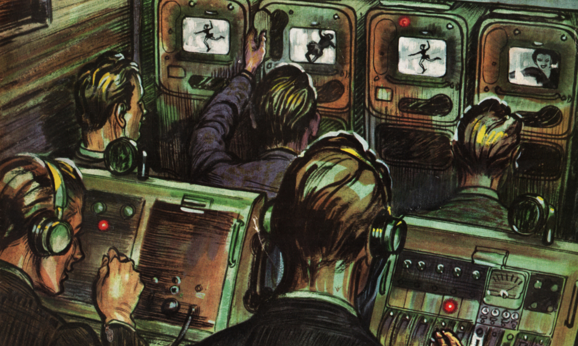
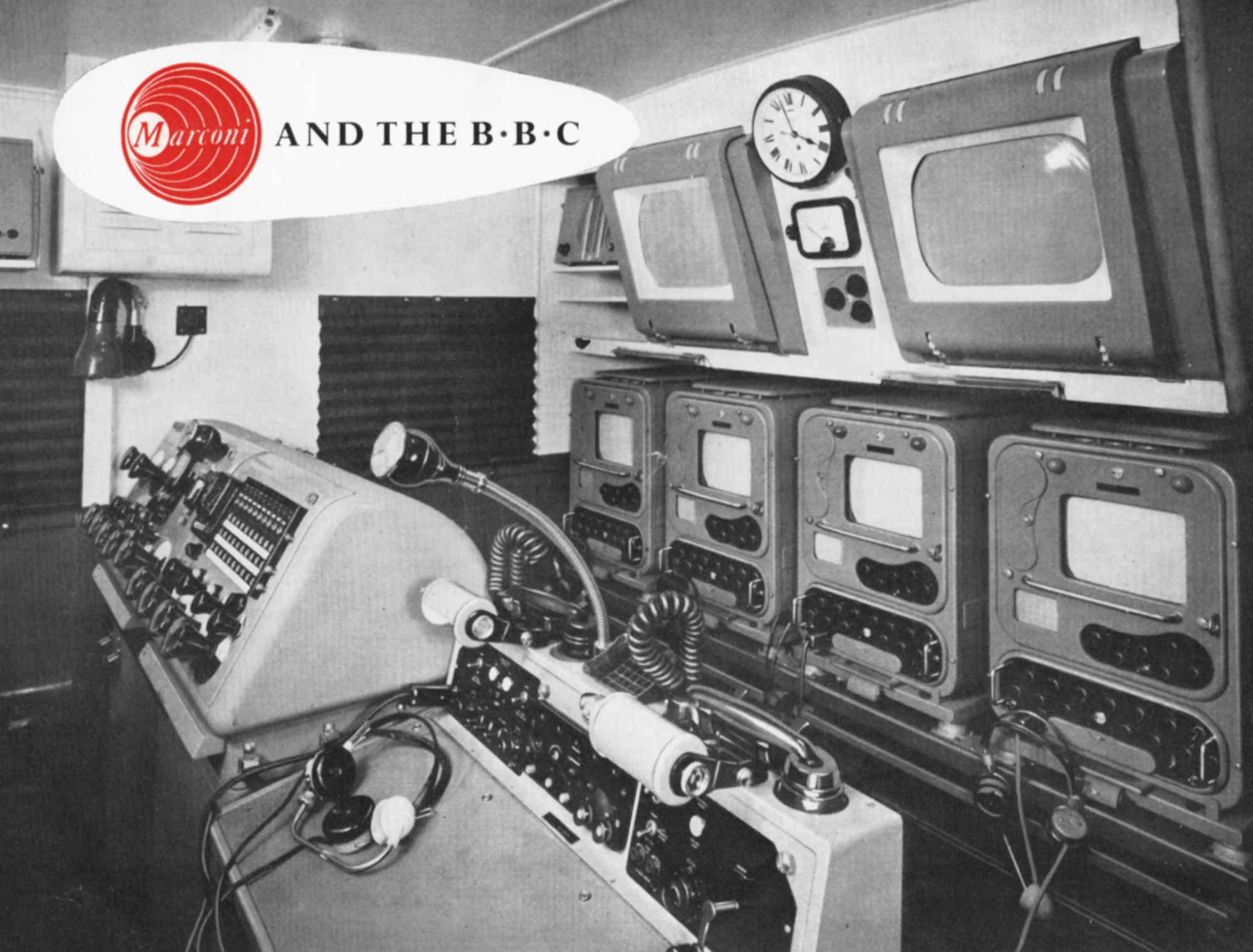
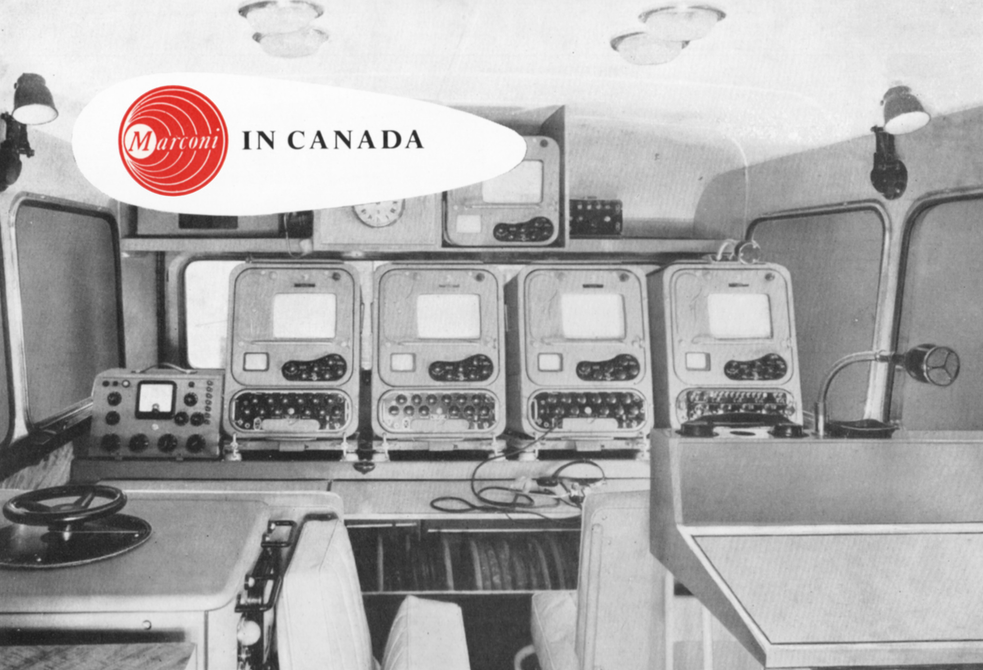
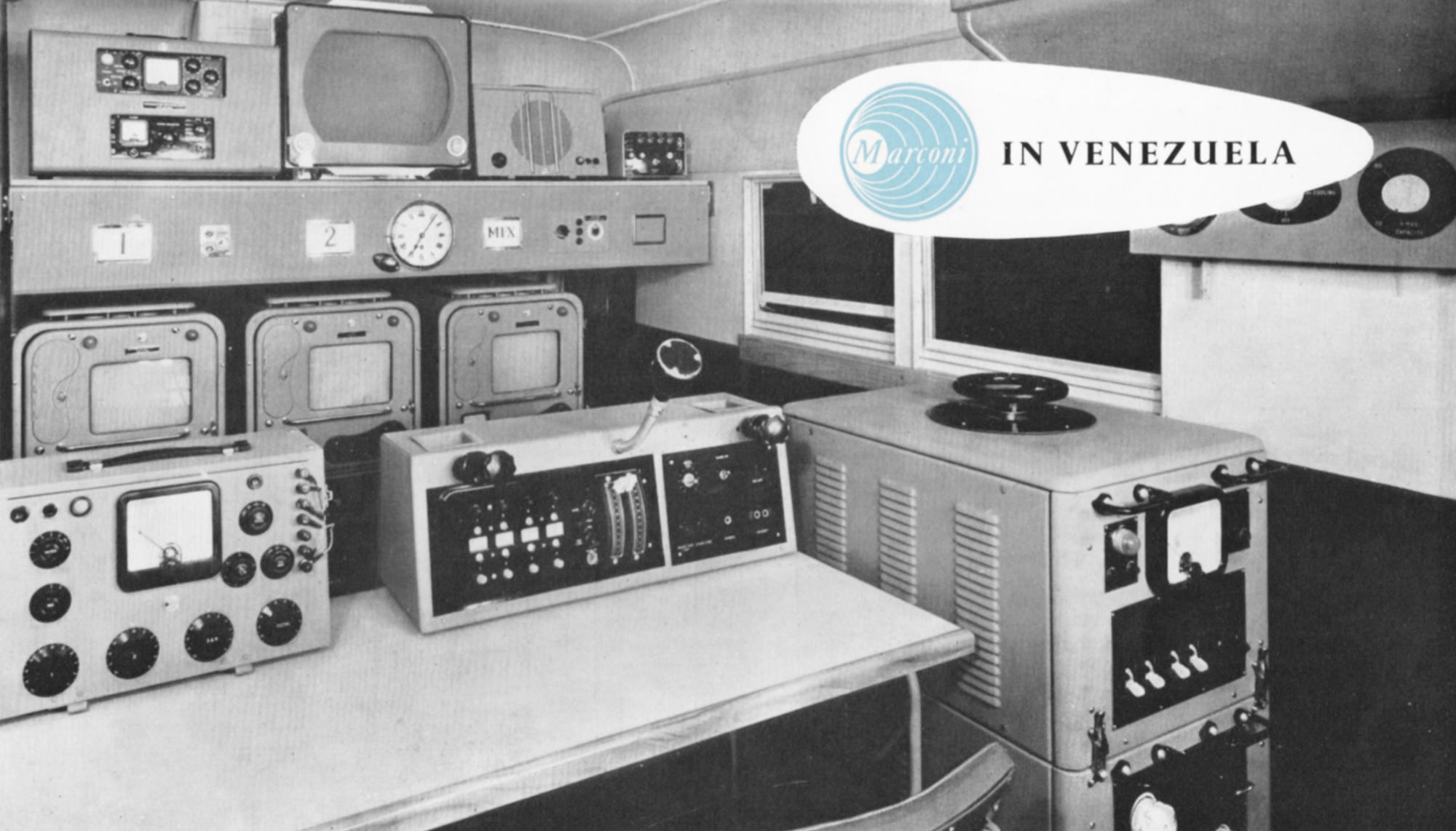
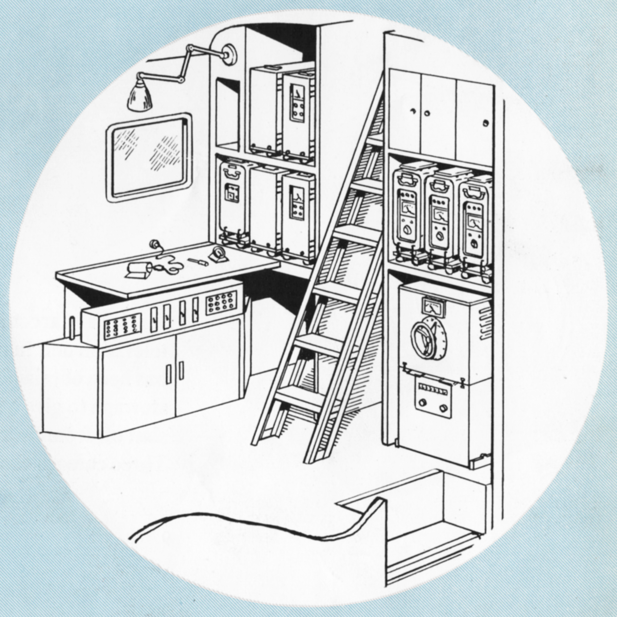
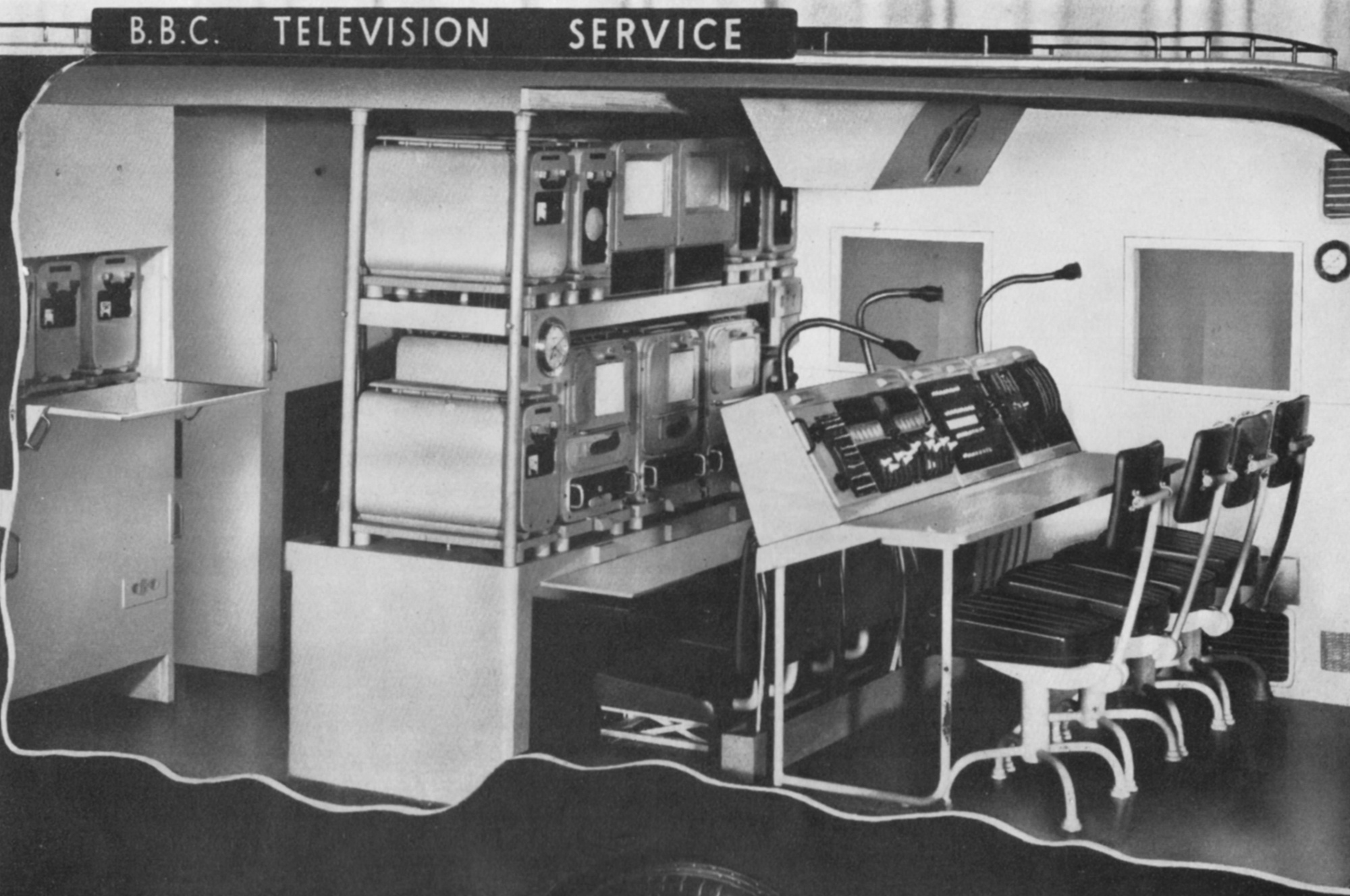
It is considered sufficient to operate a maximum of three camera channels from one mobile unit. Each channel has its own control and monitoring equipment, power units, etc., and feeds into a vision mixer. Synchronising signals are added and the final selected output is fed back to the main station or television centre. In general, each vehicle may be divided into three main parts — production position, control position and servicing area. The first of these provides for sound and vision mixing and the vehicle is so built that when seated at the controls, the producer has a clear view of all the camera control monitors. There are three camera control units which are arranged in a row side by side: each has its own monitor. A fourth monitor is provided for the use of the producer and is operated in conjunction with the vision mixer. An RF monitor is mounted centrally and above the camera control position.
The production and control positions may face either towards the rear of the vehicle or towards the front. In the latter case greater economy in cabling results and the servicing area may be completely shut off from the production area.
The power units, voltage control unit, synchronising generators, etc., are fitted in racks in the part of the vehicle immediately behind the driver’s cab. A ladder is provided to give access to the roof through a sliding hatchway. The cable drums are located in a well at the rear of the vehicle.
All units are shock-mounted and the whole of the control equipment may be built into a facia panel to give a neat overall appearance. Each vehicle is completely self-contained, suitably heated and ventilated, and lighting and power points are conveniently disposed around it. Both sound and vision links may be carried and space is provided for mounting these in the vehicle during transport.
‘Roving Eye’
A recent innovation in the world of television is the use of ‘Roving Eye’ — a truly mobile pick-up unit which is complete with camera and transmitting equipment such that a live programme can be broadcast whilst the vehicle is actually in motion. This technique has been used, with much success, by the B.B.C. and its great advantage is the ability to put a programme on the air at a moment’s notice.
The whole equipment is stowed in a 1½-ton van so that the vehicle falls into the light duty class and is not restricted by speed limitations and so on.
The layout is such that the vehicle is divided into approximately two halves, to provide a camera operating position in the forward part and a control position at the rear. The camera is mounted so that it can be raised and lowered easily whilst, at the same time, complete panning freedom is afforded. A sliding hatch in the roof permits sufficient elevation to be obtained. Room for the commentator and for a monitor is provided in front of the camera. The control compartment is neatly arranged to give the camera control operator access to all units, as required during operation, whilst seated in the operating position. As well as vision and sound programme control facilities, provision is made to regulate the motor alternator from a simple control panel.
Programme transmission back to the main studio is over a VHF link, separate transmitters being employed for sound and vision channels. A Yagi aerial array is employed for the vision link and this may be rotated when the vehicle is on the move. A 10-watt VHF transmitter/receiver provides a communication channel whilst the sound transmitter is rated at 25 watts. In both cases, a whip aerial is employed. All units are shock-mounted and draw their power supplies from a motor alternator set which is housed in a blimp, centrally positioned in the vehicle. The whole vehicle is completely self-contained. It has an operating range of up to ½-mile radius from the main pick-up point in built-up areas and approximately three miles in open country.
Mobile television in its finest sense is provided by the ‘Roving Eye’ and its greatest application is found in cities where the operating link is a short distance. The camera channel employed is of standard type so that the technical performance compares favourably with that of any outside broadcast.
Typical schedule of equipment

Representative for a standard ‘Roving Eye’ unit
| Quantity | Item | Reference |
|---|---|---|
| 1 | IMAGE ORTHICON CAMERA | A |
| 1 | CAMERA-CONTROL UNIT | B |
| 1 | PICTURE AND WAVEFORM MONITOR | C |
| 1 | REGULATED POWER SUPPLY UNIT | D |
| 1 | SYNCHRONISING GENERATOR | E |
| 1 | FOCUS SUPPLY UNIT | F |
| 1 | SOUND AMPLIFIER AND MIXER | G |
| 1 | VHF TRANSMITTER/RECEIVER | H |
| 1 | VHF SOUND TRANSMITTER | J |
| 1 | VHF VISION TRANSMITTER | K |
| 1 | COMMENTATOR'S MONITOR | L |
| 1 | COMMUNICATION UNIT | M |
| 1 | YAGI AERIAL ARRAY | N |
| 3 | VHF WHIP AERIALS | O |
| 1 | MOTOR ALTERNATOR SET | P |
Marconi Mobile Television
MARCONI’S WIRELESS TELEGRAPH COMPANY LIMITED
Head Office: Marconi House, Chelmsford ∙ Telephone: Chelmsford 3221 ∙ Telegraphic Address: Expanse, Chelmsford
Printed in England ∙ 30054/1000 ∙ Transdiffusion presentation